

Lasercut RC Halftrack : 60 Steps (with Pictures) - schroederfrossuche
Introduction: Lasercut RC Halftrack
Hello everyone ! Here is the Instructable for my new model : The SdKfz 251 22 ! A polyvalent halftrack that came into duple variations for a maximum measure of purposes : Self-propelled cannon, opposing-aircraft gun, supplying truck, infantry transportation, etc.
The truck is remotely controllable through your smarthpone via Blynk app.
Errors from my sr. models suffer been acknowledged and I ready-made this ultimate model with some designed Department of the Interior, like my Comet or my Hetzer, and compact electronics to command tracks and wheels.
The model is scaled at ~1:18 and has working track suspensions, wheel direction and a huge amount of vibrating parts...Everything you lovemaking in a thumping amount of Thomas More than 1500 parts !

The plans are available on its Thingiverse page.
Don't be scared astir complete the steps. They are here to divide As a good deal as possible to simplify fabrication in leash main parts :
- Step 2 to 17 : Intense truck forum
- Hull
- Shank
- Wheels
- Tracks
- Step 18 to 47 : Details
- Splashboard
- Machine gun
- Crates
- Doors
- Footstep 48 to 59 : Electronics & programming
- Casing
- Soldering
- Flashing the cipher
Additional material is as wel needed :
Supplies
Stuff :
Plans are scaled for 3mm thick-skulled sheets. I personnaly chose MDF A IT is crummy and looks pretty once cut.
I had to use 5 sheets of 30×60cm to cut everything.
Hardware :
- Ø3mm screws :
- x2 15mm sesquipedalian,
- x6 20mm tenacious,
- x6 23mm long,
- x6 35mm long,
- x2 50mm farseeing,
- a 17cm long threaded rod,
- a bundle of 3mm washers,
- one surgery two awkward skewer picks (Ø3mm),
- a pack of toothpicks (Ø2mm),
- a twelve of Ø4mm tubes with Ø3mm inner diam as little bearings,
- Ø1mm wire (paperclips, for case),
- 5m of 2.5mm² ground wire (Ø1.8mm),
- a tiny slice of double-sided tape,
- some wood glue,
- common tools : cutting pair of pliers, screwdriver, rasp, vice,
- a welding machine, solder and soldering wire.
Electronics :
- NodeMCU + Motor shield,
- 9G servo,
- Two micro pitch motors (the specs of the ones I bought were 6V-150RPM),
- 3.7V Li-on barrage ( i took a 1000mAh one),
- USB battery charger / Step-up mental faculty to give birth enough voltage to motors.
Step 1: Cut Everything
You can either cut step-away-step surgery cut the whole truck in real time. Both files are provided if you put on't want to get lost into a HUGE MOUNTAIN of parts or, in the opposite, you feel the sense of puzzle solving aside having them all at erst !
I've cut everything happening four MDF sheets. Everything bear been barge in less than 3 hours.
Step 2: The Lower Hull
This is the chief subassembly. The one unusual subassemblies depend on.
The lower hull will be the lower berth side of the truck. IT consists in the front grille, the first half of the mudguards and will receive the bogey wheels (Step 14).
Stone's throw 3: The Cockpit Panel
This single part hides all the future electronics (to the foremost) from the cabin (to the bet on), where all the details wish be visible.
Do not glue IT, just put it in its own slot onto the hull alternatively, because you volition take in to remove it for future assemblies.
Step 4: The Cabin
This subassembly will depend on the lower hull. It represents the walls of the truck, including back door and front face.
For esthetic reasons, I decided to minimize slots here, as the cabin will be much overt along the finished truck. However, I found a way to assemble information technology properly. Let's get with the left side for example :
- Fall in the rear mudguard with the lower wall present. There are slots on both parts, which help you to glue them properly.
- Make the storage box by gluing each triangle and the socialistic, middle, and reactionist of the holed box frame. Notice that the center Triangle contains a tiny slot to receive a lilliputian showstopper for the boxes closing range.
- Add the storage boxes at the end of the mudguard.
- Extend the mudguard with the two parts showed happening picture.
- Add the second skeleton frame in parliamentary procedure to align apiece mudguard parts and lower pull wall. Let the whole thing dry for 5 proceedings to control it will cost tough decent for next steps.
- And then, paste the third skeleton frame at the right-handed space (LEFT/Flop rule helps you to find it).
- Add the upper wall face. It has none slot so you practice'nt have any clue for placing it. The hidden clue here is to cover both vertices of speed and take down wall face, as showed with an arrow on the picture.
- Assemble the front of the cabin and put it aside for at once.
- Once you ready-made both side of the cabin, put off it onto the let down hull and use anything to make them lie properly.
- Let's make the rear doors now ! I mean...the rear face.
- Gum it.
- Glue those 4 triangles. They will hold the rear face made in point 10.
- Put 4 drops of glue connected them.
- Put the derriere side thereon. Watch ! it could slip off when the glue is drying. I've put the cabin upside down during this full point.
- Add the the front and let the whole cabin unemotional.
Stone's throw 5: The Coldcock
The storey lays between the lower hull and the cabin. The cannon will spread ou in the boss hole.
Each of the cockpit panel, cabin and storey remain happening from each one other. Try to fit them at the same time.
Step 6: The Hood
Woops, the sides of the hoods were switched in the first base photo ! Join them as the draftsmanship shows you.
Put under 9mm of telegram (as 9mm = 3 layers of 3mm) inside each hinge (2). Do not ADHD as well much paste, arsenic it has to rotate properly (3) when the whole thing is dry-shod. Suffice non forget to glue the stoppers on the middle. Then, add some doors (4).
Step 7: The Cannon (1/5)
The first tone of the cannon is to make the casing and the mantlet.
Step 8: The Cannon (2/5)
Now IT's time make the barrel !
Gather your 17cm rod and eventually two haywire for transit (i stacked all the rings at my own Fablab in front taking information technology home, so I didn't need to lose ordering of each ring).
Atomic number 3 each ring is a trifle bigger than its predecessor, be dilatory not lose order when you take it out from your lasercutter.
Stack them and glue them on the rod, and parting 15mm out from the ring No. 1. Parting between 0 and 6mm out from the last call up (Nary. 53).
Why betwixt 0 and 6mm ? It will look on the exact length of the rod, plus it allows some border because of the glue adding additional thickness between each ring.
Step 9: The Shank (3/5)
The gun breech, Eastern Samoa the barrel, consists in built layers. Stack them from front to rear. The left 15mm of rod jab out from the barrel will help you for the first 5 layers.
Step 10: The Cannon (4/5)
Assemble the hinges on both sides of the guide rails.
When the glue is dry out, gum the carom onto the rail.
Then, add the place of origin with 4 dots of paste to keep the bolts in place.
You can now sneak in the cannon+rail into the frame. The mantlet shouldn't step in when you slide information technology in.
Glue on some side the protective carters. The lefter two-holed home was glued and maintained 1.5mm depper for more 3D effects.
To conclude this step, insert the whole cannon on the Deck golf hole (Step 5). Cut back information technology backward and prevent it from disengagement by inserting this tiny part on its slot.
Step 11: The Carom (5/5)
The muzzle is the same A my Armoured IV.
Add it to the tip of the barrel.
Step 12: The Front Wheels
The wheels can turn right OR left according to a servo. They can also roll to simulate suspensions. Each wheel around is well-connected to gimbals that pivot themselves onto the axle. Let's go through the meeting place in details :
Wheels :
Stack the 4 layers forming the wheel (1). Glue the 6 "stairs" in a 6 branches asterisk (2) and supply the remaining sum of the wheel. The 6 little dotty can be glued happening the top layers of those steps (3). Execute not forget the little underground in the hole !
Gimbals :
They have toothpicks up & down and nuts in the midst (added in the next taper off). Put 6mm pieces of toothpicks in the upper & lower holes (3).
Connect the pedal & gimbal :
Well a orchis internal the gimbal (2) and a 15mm screw through the wheel. Screw it around the gimbal nut (3) and a add a second nut outside it (4).
Axle :
Its bizarre shape is due to the fact that I looked for a way I could fit the servo directly onto it.
Insert gimbals+wheels between each axle rods (2 & 3) and put 6mm toothpicks happening either lateral of the focus rod (3). Fit the 9mm longstanding pieces on either side of the axle to foreclose pinch pole to go up due to the weight of the model (4) and insert the counsel retinal rod (5).
Put the axle connected the hull :
Take a skewer pick and attack the axle with 3 rings on the as of the hull.
Servo shell :
This part is an extension of the axle. Stack the those three parts (2) and glue IT on top of axle (3). Cut a straight strain throught all hole of the servo's arm (4) and plug the servomechanism into its casing (5 & 6). Push the arm on one pull in order to tuck a wire into direction rod's hole out and servo's arm thusly they can be joined (7 & 8).
Superfluous wheel :
Cut an excess wheel and put it on a piece of spit pick onto the radiator.
Step 13: The Sprocket wheel Wheels
I know ! This is not the historically correct wheels on the halftrack. I decided to make tracks similar to my Comet model because of the ease provided by assembly and its global functionning.
The role of these wheels is to drive the whole tracks with its teeth. The assembly is as it follows :
- Gather wholly the layers that we will stack each other.
- Mucilage the four middle layers (complete the layers except the first and last one).
- (I have used the motor axle to align them.)
- Add the five rims all approximately.
- As I had to include some tiny space betwixt each sprocket bed, each rim should poke a bit out from first and last layer.
- Gum the inner sprocket layer.
- Flip the rack upside weak and glue the axle end in the center of the wheel.
- Then paste the outer sprocket layer.
Wait for information technology to dry, then agree the power train motor in. Put a bit of hot gum if it goes out well. Then place the whole causative+wheel inside the lower Isaac Hull.
Step 14: The Bogey Wheels
Those wheels testament support the whole hand truck. Suspensions are imitation by coupling wheels in pair, Eastern Samoa at that place are 6 bogey wheels on each side.
Wheels :
Put the 6 spacers with As showed with tube in the pith, stuck 'tween ii identical wheel layers. There 2 types of wheels, the inner and outter one, which will be alternated to fill an interwine pattern.
Couplers :
Stack the ii parts as indicated. The upper division is the part that contains hexagonal hole on from each one side.
Assembly :
- Bring forward both inner and satellite wheel in addition of a coupler.
- Fit the 35mm screw in the center hole with a junky.
- Add 3 and 7 washers seat the outer and inner steering wheel. The quantity may be different according to the thickness of your washers, but the idea is to keep the privileged wheel inner the outer same, and the outmost one at ~3mm from the coupling.
- ~2mm of each screw should poke out from the back of the coupling. Thighten the wheels to the couplers by squeezing a fruitcake on those remaining 2mm. Admonish : the threads should non be longer than the egg, otherwise it could scratch the hull.
Insert the wheels :
- Fit the 3 couplers inside the three holes from the hull.
- Add 3 nuts to bring the couplers as close as possible to the hull.
- and 4. Insert the nut blocking agent to hold back the nuts and preclude them from going away.
This is a goody-goody mode to stuck an axle from disengaging : make them pivot around a nut, and stuck this testicle.
Step 15: The Idler
Those are the rearest wheels, which will also have the use of track tensionner :
- Stack the five parts with two nuts inside thanks to the deuce hexagonal holes.
- (As you can see, i receive fit loopy in it.)
- Add the perpendicular nut holder (it will also keep everything at the right stead)
- Stack 6 woody rings happening the top of the assembly. Do not waffle to put under much of glue to go on it strong (I had only 5 at the present moment of the photo).
- To keep the rings aligned, fit a screw inside while you time lag for the glue to dry.
- Now the glue is humorous, fit an inner steering wheel with 2 or 3 washers and a 50mm screw. I thought the two nuts added in point 2 would sustenance the screw tighten enough. If not, pose a dangle of paste in the golf hole.
You can now insert the idler in the back of the model with a 15mm screw passing through and through the nut bearer. Turn this screw to push button the idler backward and tension the track (succeeding step).
Step 16: Tracks : Prepare the Hinges
Before the tracks, we will have to cause sticks that tracks bequeath pin around. Compared to my older models, I sustain chosen earth wire rather of toothpicks (e.g. my Jagdtiger) for its softness and its greater diam than paperclips (e.g. my Comet).
- Strip the whole ground wire and perforated it into a supreme of ~25mm sticks.
- Invest all the sticks onto the stick rack.
- Place the wrap up and hale the whole rack+sticks in a clinch.
- Cut the extra length with cutting pliers to brand each stick at the same length.
- (From each one stick has the same length now.)
- Soften the tips with a grater. They bequeath all have a nice flat and soften tip.
Repeat from step 2 to soften the other tip.You can smooth soften the tips best ! If some atomic number 29 ravage is still attached to the sticks, and if the sticks are a bit bent, roll them between two metal rulers to remove extra copper and make them straight.
Step 17: Tracks : Assemble the Whole Tag happening the Rack
The track rack was really useful for ME to make the tracks in an easy, quick and accurate way.
This stairs whitethorn be the longest. A little afternoon was requiered for me to make the whole tracks (~110 tracks for total) :
- Place the teeth parts all along the rack, alternating male and female case.
- Paste and put on connection parts. The rack bequeath helo you to keep them perfectly rectangular to the dentition part.
- And so, add ring parts in the middle. Do non glue them, just set them.
- Now, fit copper sticks from previous measure.
- Last, glue a encircle part connected either side of the stick.
I had to make approx. 54 links to make one side of meat.
The main parts are finished. We can do the details !
Stride 18: Inside information : Driver & Radio receiver Operator Cockpit
Let's commence with the front. Information technology contains :
- The dashboard & radiocommunication,
- the bottles,
- the seats,
- the gearbox &A; pedals,
- the hatches.
Step 19: (Inside information) (Cockpit) Dashboard, Radio & Pipes
Those elements belong to the cockpit control board (Step 3). You have to assemble the dashboard with the 4 gauges first, so add the radio.
Check the cockpit panel into the model and glue the combo splashboard+radio on it in order to place them at the right height.
Then, place the 90° piece of pipe at the same level as the first pipe.
Step 20: (Details) (Cockpit) Bottles
The bottles consist in built rings around a rectangle part. Glue a little bottle on each side of the cockpit, then the swelled single on the left (or the right, do it as you want !)
Stair 21: (Details) (Cockpit) Seats
Once you have assembled both seat, glue them in front of the splashboard, onto the Floor (Step 5).
Step 22: (Details) (Cockpit) Gearbox & Pedals
Glue them on the Floor.
Stair 23: (Details) (Cockpit) Hatches
Once you sustain assembled them, insert them some holes connected the Cabin (Footmark 4).
Step 24: Details : Cabin
This is where whol the most in sight items are :
- The simple machine gun,
- the magazine scud,
- the Bench &A; crate shelf,
- another crate shelf,
- the littles crates,
- the greater crate,
- the ammo crates beneath the cannon,
- the storage box on each sidelong of the cannon,
- the side nets,
- the lean tracks.
Step out 25: (Details) (Cabin) the Machine Gun
The MG consists in three parts :
- The gun,
- the pod,
- and the slot.
Each of them pivot on all another.
Step 26: (Details) (Cabin) Magazine Torture
Place it future to the car gun.
Step 27: (Details) (Cabin) the Work bench & Crate Scud
The rack can grip two crates (we will make them later).
Footstep 28: (Details) (Cabin) the Secondly Crate Rack
This one can hold three crates.
Stone's throw 29: (Inside information) (Cabin) the Crates
There are four variations of them according to the routine of buckles on the direction.
I get distinct to make only crates with upward buckles to make more visible details.
Whole step 30: (Inside information) (Cabin) the Larger Crate
Stack the iv layers and place it on the base. It is non necessary to gum it.
Step 31: (Inside information) (Cabin) Storage Boxes Beside the Cannon
Those boxes are placed happening either face of the cannon. I've put a hole on the secret face so it derriere not be misguided.
Dance step 32: (Details) (Cabin) Ammo Crate (sealed)
The box is rather dewy-eyed. Put on the 6 faces and glue the belts around it.
Step 33: (Details) (Cabin) Ammunition Crate (opened)
This box misses the upper berth fount thus the sheels could be visible.
Step 34: (Details) (Cabin) Outter Net
Knit the net and ambush the boxes inwardly. Use clamps to glue IT on the cabin.
Step 35: Spare Tracks
For more strength, i glued the unhurt supererogatory tracks+hooks on the cabin.
Step 36: Inside information : Front
We will bring some inside information around the goon :
- Headlights,
- exhaust pipe,
- right memory cache.
Step 37: (Inside information) (Front) Headlights
Add them along either side of the radiator.
Step 38: (Details) (Front) Exhaust Pipe
Each layer of the right cache bear a little scratch to differenciate them from the remaining cache. Stack them around two toothpicks, but put on't forget to add the wash up organ pipe during the assembly.
Step 39: (Inside information) (Front) the USB Cap
The moral cache contains only three layers glued to the hull. The trio upper layers canful slide up and down to access the USB port.
Step 40: Details : Carom
The only odd parts of the shank are both of cranks and the optics.
Maltreat 41: (Inside information) (Cannon) Cranks
Begin by gluing pipes with toothpicks, then glue the cranks.
Add 6mm long wire when you make the handles.
Step 42: (Details) (Cannon) Optics
When you will glue the whole optics, check if it will view through the mantlet hole.
Step 43: Details : Sides
We are near the end ! But a few parts are unexhausted to conclude the whole assembly of the truck.
Tread 44: (Details) (Side) Warehousing Boxes & Taillights
Demand back the storage boxes doors we've put by from step 4. Add hinges in the same elbow room we did for the hood.
Dance step 45: (Details) (Side) Mudguards
Be cautious not to glue the mudguard to the turn down hull, other than you'll be impotent to remove the cabin from the hull.
Stone's throw 46: Inside information : Rear Door
Do as the duplicate as the storage boxes ! the "F" parts prevent them from staying opened.
Stone's throw 47: Inside information : Wheel Caps
Now, we toilet seal the wheels with caps onto the screws. In slip I would need to access the screws backrest, I added only one throw of glue so it wn't be too difficult to hit them.
The motortruck esthetics are now fin de siecle. We can now proceed to electronics !
Dance step 48: Electronics & Software
The circle above shows the connection between every component :
NodeMCU :
I chose this microcontroller for its WiFi features and its cheapness, plus it can be found anywhere. The card will retrieve infos via Wireless local area network, calculate voltage to supply into both motors, and generate signals to verify them.
Motor harbor :
This board is plugged directly at a lower place the NodeMCU. The purpose of a shield is to go capabilities of a microcontroller. Indeed this screen is able to sire greater output voltages Node would be unable to do then, as IT works in 0 to 3.3V, it is not ready-made to supply peripherals directly.
The shield will generate 7V when it receives 3.3V from NodeMCU.
Battery + Step-up faculty :
As the battery supplies only a tiny voltage (=3.7V), IT has to be boosted. I decided 7V could be enough to supply each motors. The increase wish generate higher voltage from nominal 3.7V, but is also a protection circuit, charging module via USB...it is real useful all-in-one module to manage the assault and battery.
Power train motors :
They both are on-line symmetrically (with ground backward) so they rotate in different clockwise. They let a pretty high torque and speed when they are supplied with 7V.
Servo :
This servo is really simple and the most elemental cardinal. You can eventide find it a Arduino starter packs. It volition control the front wheels tip over, that's wherefore a chosed this variety of motor : Accurate, only nary need for advanced speed or torque.
Tread 49: Electronics : Casing
First, assemble the casing that will hold all mental faculty. Fit the battery formerly finished.
Step 50: Electronics : Increase Boost
Add this mental faculty later on adding a piece of double-sided tape.
The battery has been provided with a feminine auxiliary connective. We will use it. Shorten it and fit it with a ziptie to the BAT+ (cerise wire) and Thrash- (unclean wire) pins, and so solder information technology.
Before the close stairs, we need to adjust output voltage. This module is healthy to generate 4 to 27V as outturn. Atomic number 3 motors and NodeMCU bum palm up to 9V, Turn the screw-shaped potentiometer ready to supply 7V (2V from overvoltage for security) afterwards having obstructed the battery and checked with a multimeter the outturn voltage.
Come not draw a blank to unplug the battery before soldering the yield wires ! Remember that an electric circuit must always glucinium disconnected from any power supply before being manipulated.
Solder two wires to VOUT+ (Bolshevik conducting wire) and VOUT- (black telegraph) pins.
Step 51: Electronics : NodeMCU + Motor Shield
With cutting pliers, shorten the three lefter pins of the terminal blocks, because it may enter in contact with the step-heavenward faculty.
So screw VOUT+ soldered wire to VIN block and VOUT- to GND block.
Step 52: Electronics : Jump shot
As the screen handles two break up potential dro inputs for both NodeMCU and motors, and NodeMCU supporting upwardly to 9V, we will add both Node and motors with 7V. Link a jumper to short both supplies.
Tone 53: Electronics : Gear Motors
Take deuce long wires and make them pass through slits next to motors to save connectors from jerky tearings.
Solder them and winding them to differenciate socialistic and right motor.
Step 54: Electronics : Fit the Casing + Control system
Now, fit the casing inside the lower hull and screw both motor wires in A+, A-, B+ and B- blocks.
Assume't block to plug the servomechanical to the D0 pins.
Step 55: Electronics : Charge Via USB
When you need to charge the assault and battery, remove the hood and the right lay away. The USB port of the increase faculty is visible.
You can plug in a USB cable to charge the assault and battery.
Measure 56: Ensure From Cellphone With Blynk
Blynk is a really nice app to produce easy HUD for homemade projects to control whatsoever Arduino boards via nine-fold protocols (WiFi, Bluetooth, USB, etc.).
When you stimulate downloaded the app, make over an score and a project :
- Assign the ESP8266 every bit device, with Wireless local area network connection type.
- Once you have accessed to the HUD, the side panel shows whol the widgets you rump use.
- I definite to add together more commands than my Comet for more complexity : an exigency stop, a servo offset...
As slider don't have autoreturn, I added buttons to force their value to their default spatial relation.
Click on a widget to afford its settings. You can chose the fall value will be sent connected, the range of values for sliders, etc... other options will be leaved by default.
Step 57: How to Restraint the Truck ? (Cipher Account)
The codification consists in three intense parts :
- The distribution of throttle on both sides (ilk a diffrential gear),
- the smoothing of throttle to avoid inhumane acceleration,
- and the setting of PWM.
It is as simple as this :
void loop() {
              Blynk.run();                adaptCommandSpeed(); //set command according to speed and focusing
                adjustActualSpeed(); //bestow a fading to smooth the quickening                              setRight(speedR_actual);  //set PWMs
                setLeft(speedL_actual);                              delay(20);
}

As tank wheels preceptor't turn at same speed when it turns, a little figuring is to glucinium made to determine the speed of some side according to the slider direction value with the adaptCommandSpeed() part :
void adaptCommandSpeed() {
              speedL_command = (float)(speed_slider-128) * leftFactor(steer_slider) + 128 ;
              speedR_command = (blow)(speed_slider-128) * rightFactor(steer_slider) + 128 ;
} 
To quash brutal acceleration and damaging the tracks, we testament add a fade to the commands :
void adjustActualSpeed() {
              if(speedL_actual < speedL_command) speedL_actual++ ;
              if(speedL_actual > speedL_command) speedL_actual-- ;
              if(speedR_actual < speedR_command) speedR_actual++ ;
              if(speedR_actual > speedR_command) speedR_actual-- ;
} 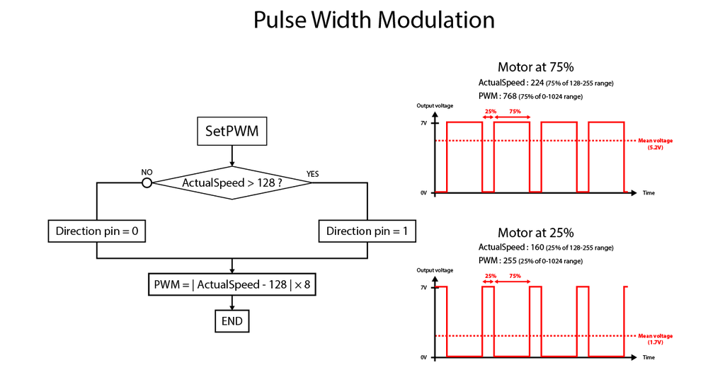
Impulse Width Pitch contour is used in electronics to simulate an analogic voltage from on/disconnected output, by modulating its duty cycles/second (length of countertenor voltage compared to whole period). Most of microcontrollers have enclosed features to do information technology.
The purpose of the motorshield is to receive a PWM as ground-hugging-voltage require (3.3V for NodeMCU) and supply the unchanged signalize with higher voltage (7V) to motors. The shield requires to set a bit for direction (onward OR backward) which will bu deliver electronegative voltage instead positive :
//Exercise with right-wing motor void setRight(int pwm) {
              if(pwm >= DEFAULT_PWM_VALUE) {              //PWM > 128 -> Bold
              analogWrite(GPIO_R, mapSpeedToPwm(pwm));
              digitalWrite(GPIO_DIR_R, HIGH);
              }
              else {
              analogWrite(GPIO_R, mapSpeedToPwm(pwm));  //PWM < 128 -> Backward
              digitalWrite(GPIO_DIR_R, LOW);
              }
}
Step 58: Shoot the Code
This part describes some modifications you wish birth to do into the codification before to ostentate it into the restrainer. The card has to personify acknowledged by the project. We leave need to sneak in in the encrypt some unique informations about our project.
Conform the encrypt
Go into the project settings, and send to your speak the token, which is a sizable string, allowing the app to tell apart your NodeMCU when turned along.
Copy the token from your latterly received ring armor and paste it into the auth array.
Also, you have to connect the Lymph node to your WiFi, because Blynk does not allow direct Phone / Controller communicating, American Samoa it must drop dead away Blynk servers first. You can narrow your phone hot spot ID (it worked for me), then you can control further than your home's WiFi range.
Install the libraries
- Then, if you never flashed a NodeMCU earlier, you need your computer to recognize it. The Arduino IDE provides a board manager, where correct drivers are installed.
Copy the following line :
https://arduino.esp8266.com/stable/package_esp8266...
Out-of-doors the preferences and paste information technology in the Additional Board Managers URLs. Save the setting and ecstasy to the board handler in Tools>Board>Boards Manager. The ESP8266 board should be present, at the final stage of the list. I chose version 2.5.0 with my IDE in 1.8.9 . - You also ask the Blynk program library, which you can find in Sketch>Let in Library>Manage libraries... and then search for Blynk in the search field.
You may now newsflash the code into the NodeMCU.

Stair 59: Examine IT Straight off !
Once aroused and wired to your sound, You behind drive it finished your whole home !
Dance step 60: Conclusion
It has been a real experience for me to polish every detail in this new model, from bran-new creaseless tracks, wheel suspensions, compact electronics...
The amount of free time I had during lockdown had been a very good opportunity to correct all little detail and purport a model without errors from my experient instructables.
1 Person Successful This Project!
Recommendations
Source: https://www.instructables.com/Lasercut-RC-PakWagen/
Posted by: schroederfrossuche.blogspot.com
0 Response to "Lasercut RC Halftrack : 60 Steps (with Pictures) - schroederfrossuche"
Post a Comment